









Engineering Plastics

PEEK CNC Machining Service

Custom CNC-machined PEEK components for applications requiring heat resistance, chemical resistance, mechanical strength, and dimensional stability. BatchMach Precision provides CNC milling, CNC turning, and 5-axis machining for PEEK prototypes, replacement components, and low-volume production parts.

  • Lead times as fast as 1 day with direct factory pricing
  • Accuracy down to ±0.005 mm
  • No MOQ for one-off prototypes and low-volume production
  • Worldwide delivery available
PEEK CNC Machining Service part

Upload Your CAD Files for a Quote

Drop your CAD file here or click to browseSupported: STEP, STP, IGES, SLDPRT, DXF, DWG, PDF

Your files are secure and confidential · Max file size: 100 MB

19+

Years of Experience

250+

Machines & Testing Equipment

11,000 m²

Manufacturing Area

200+

Skilled Staff

ISO

9001 / 13485 / AS9100D

From prototypes to repeat production, BatchMach Precision brings together two ISO-certified CNC factories, practical machining expertise, and dimensional inspection to deliver custom parts built to your drawings.

Trusted by
numerous companies

Our PEEK CNC Machining Capabilities

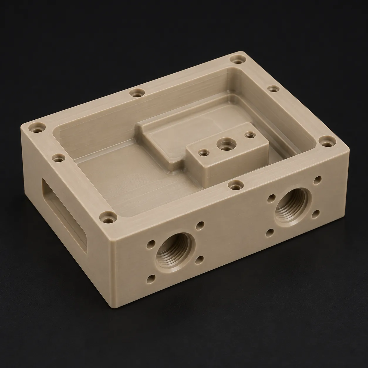
CNC Milling for PEEK Parts

CNC Milling for PEEK Parts

BatchMach Precision uses CNC milling to produce PEEK housings, fluid manifolds, electrical insulators, fixtures, and parts with pockets, slots, holes, or other prismatic features. Toolpaths, workholding, and material-removal sequences are planned around wall thickness, critical dimensions, and internal-stress risks to control cutting heat, burrs, and dimensional movement after machining.
CNC Turning for PEEK Components

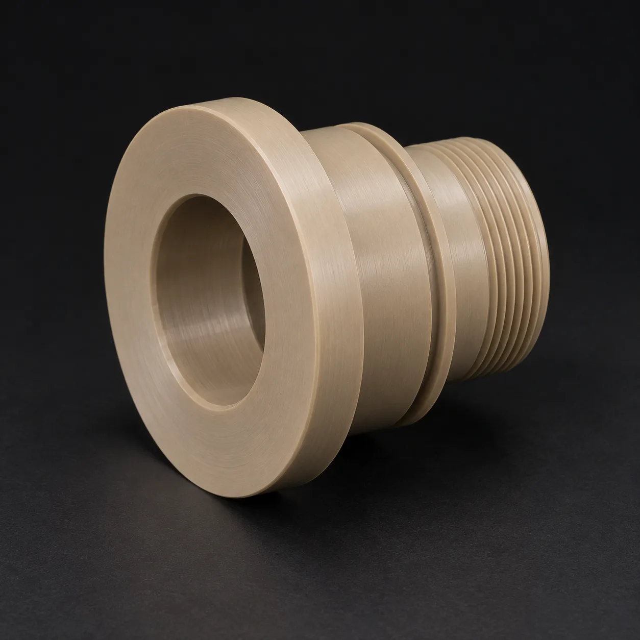
CNC Turning for PEEK Components

Round PEEK components such as bushings, sleeves, bearing parts, spacers, rings, seals, and threaded parts are produced by CNC turning. BatchMach Precision selects tooling and workholding according to diameter, length-to-diameter ratio, wall thickness, and concentricity requirements, helping maintain feature relationships and surface condition without excessive heat or clamping pressure.

5-Axis Machining for Complex PEEK Parts

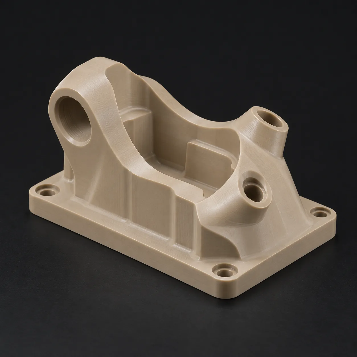
5-Axis Machining for Complex PEEK Parts

When a PEEK part combines multi-sided features, angled holes, compound surfaces, deep cavities, or closely related datums, 5-axis machining can reduce the number of required setups. BatchMach Precision uses this capability to maintain relationships between holes, surfaces, and datums while limiting positioning errors and clamping-related distortion.

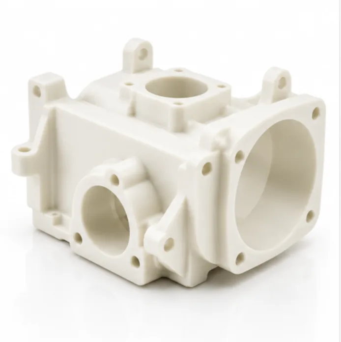
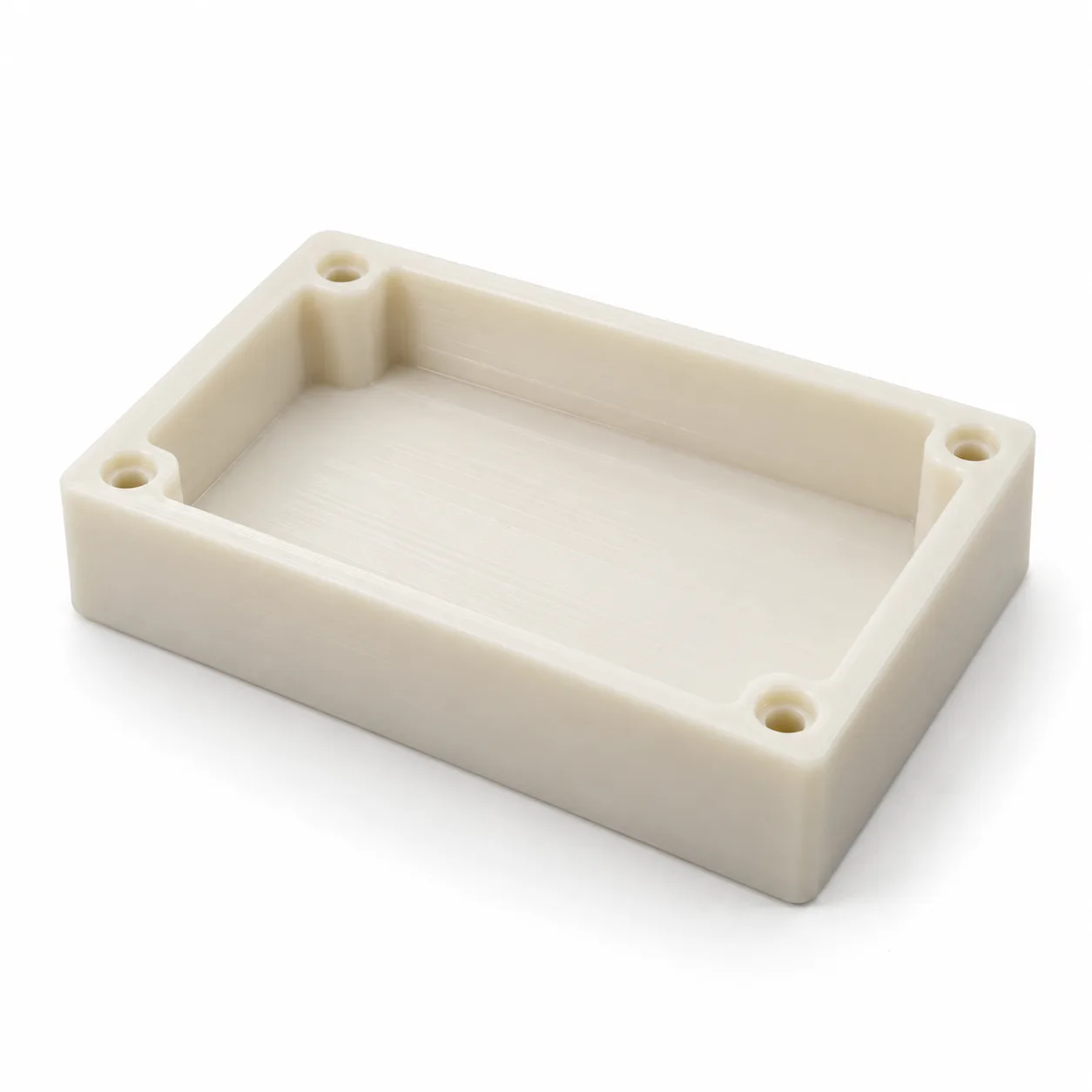
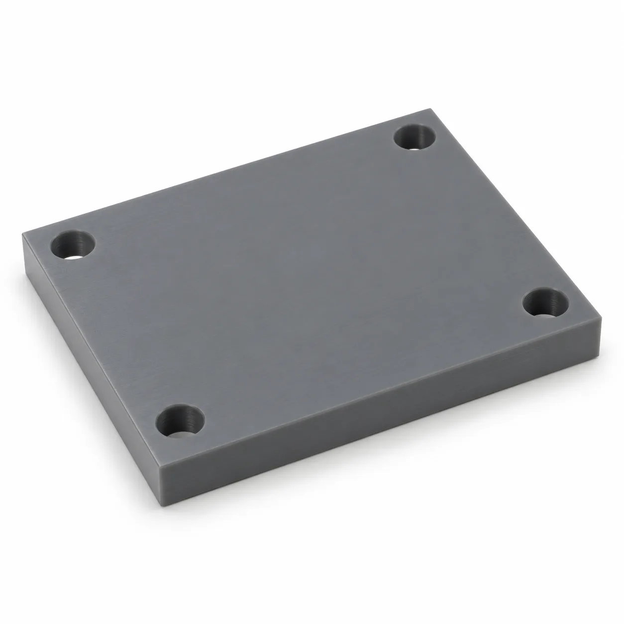
Representative CNC-machined PEEK part

PEEK in CNC Machining

PEEK is often selected when a component must retain its strength and dimensional stability under elevated temperatures, chemical exposure, or continuous mechanical loads. Machined parts commonly include bushings, seals, electrical insulators, bearing components, and fluid-control components.

Parts can be produced directly from plate, rod, or tube without production tooling, making the material practical for prototypes, replacement components, and low-volume orders. Unfilled and reinforced grades differ significantly in stiffness, thermal expansion, wear behavior, and machining response. BatchMach Precision reviews the operating temperature, load, chemical contact, mating conditions, and drawing tolerances before confirming the material and machining plan.

CapabilitySpecification
Lead TimeAs fast as 1 day
Machining AccuracyDown to ±0.005 mm
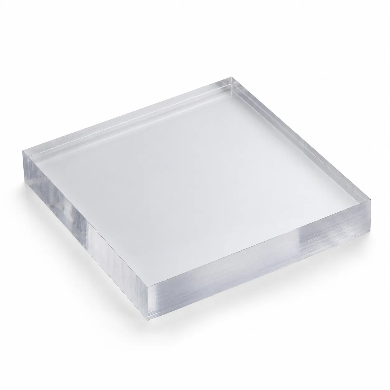
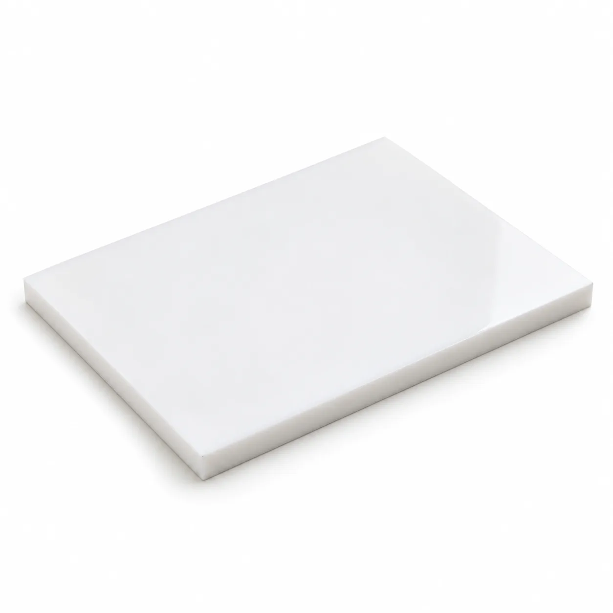
Available PEEK MaterialsUnfilled PEEK, 30% glass-filled PEEK, 30% carbon-filled PEEK, and bearing-grade PEEK, subject to stock availability
CNC Equipment3-axis, 4-axis, and 5-axis machining centers, CNC lathes, and mill-turn equipment

Typical Properties of PEEK Grades

VICTREX™ PEEK 450G — Unfilled

Unfilled PEEK for toughness, electrical insulation, and chemical resistance.

98 MPa at yield

Tensile Stress at 23°C

25%

Elongation at Break

84.5

Hardness (Shore D)

152°C

Heat Deflection Temp.

143°C

Glass Transition Temp.

Surface Finishes for Machined PEEK Parts

Surface finishing can improve the assembly, contact, sealing, identification, or appearance of machined PEEK components. The appropriate process should be selected according to the material grade, part function, critical tolerances, and operating environment.

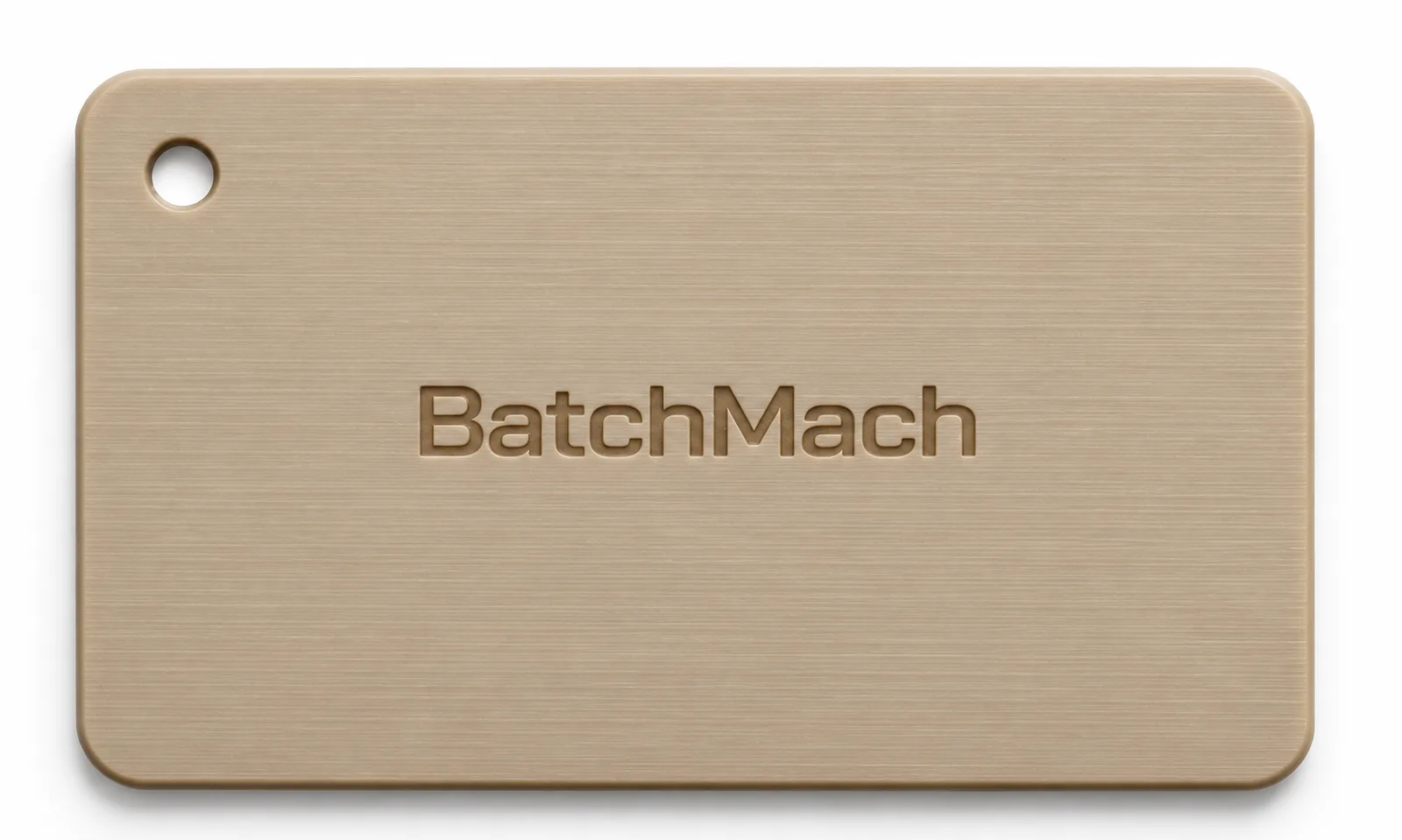
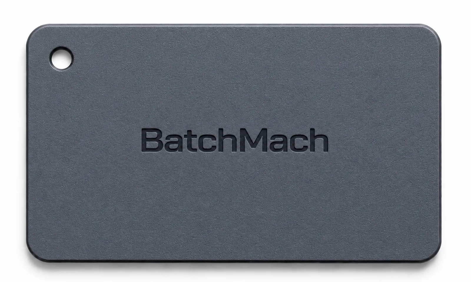
As-Machined

As-Machined surface finish sample

The part retains its natural machined surface without added coating thickness. This option shortens lead time, reduces cost, and limits the risk of secondary processing affecting critical dimensions. It is suitable for internal components, electrical insulators, and parts with closely controlled dimensions.

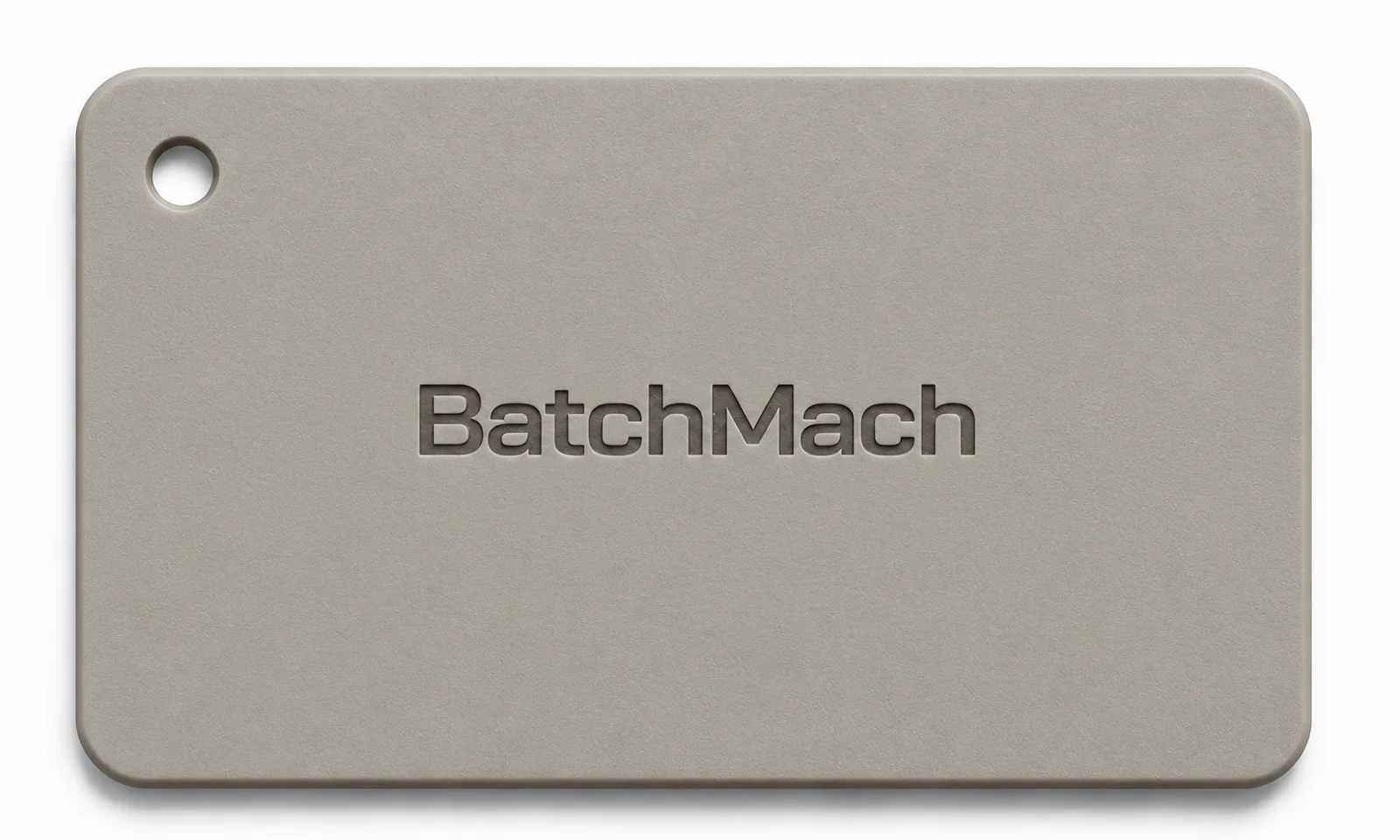
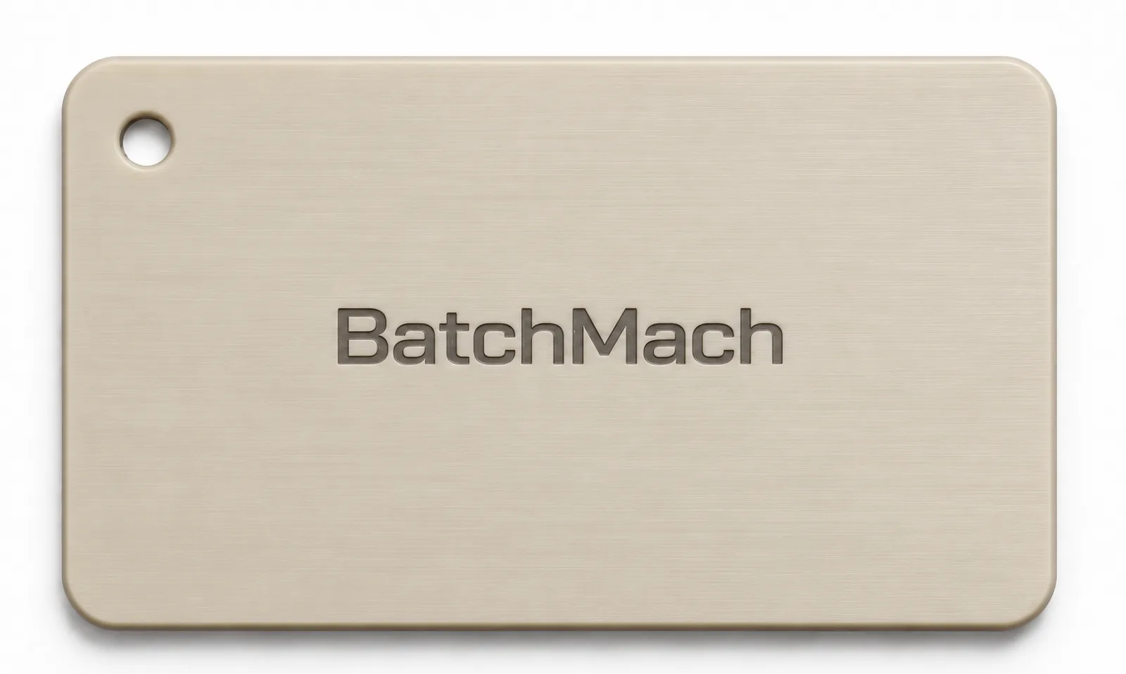
Precision Deburring

Precision Deburring surface finish sample

Controlled deburring removes residual material from holes, threads, and edges. It supports smoother assembly and reduces the risk of damaging mating or sealing surfaces. The process can also preserve specified sharp edges, chamfers, and critical dimensions.

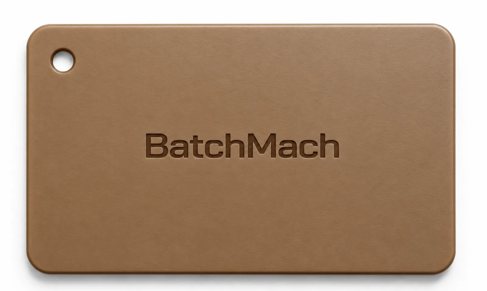
Sanding and Mechanical Polishing

Sanding and Mechanical Polishing surface finish sample

Sanding and polishing reduce visible tool marks and improve the uniformity of cosmetic and contact surfaces. On sliding, cleanable, or visible components, a smoother surface may reduce localized friction, contaminant retention, and difficult-to-clean areas. Final performance should be verified under the actual service conditions.

Fine-Media Blasting

Fine-Media Blasting surface finish sample

Fine-media blasting produces a consistent matte texture, reduces visible differences between machining directions, and helps conceal light tool marks. Controlled surface roughening can also provide a better mechanical key for subsequent coating or bonding.

Precision Grinding and Lapping

Precision Grinding and Lapping surface finish sample

Grinding and lapping provide tighter control of flatness, parallelism, thickness, and contact-surface condition. These processes are useful for sealing faces, sliding surfaces, valve components, spacers, and parts that require consistent surface contact.

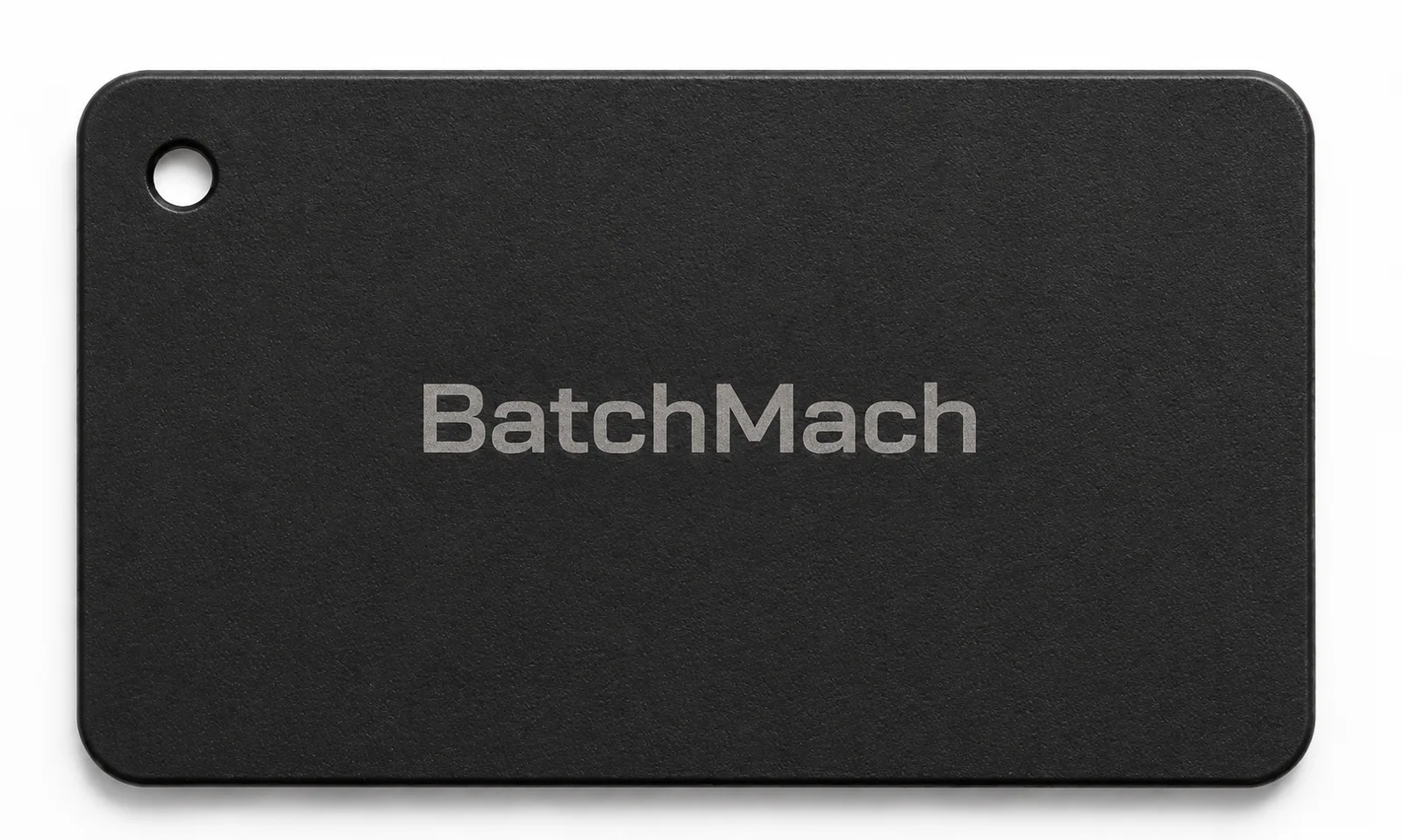
Laser Marking

Laser Marking surface finish sample

Laser marking adds part numbers, batch codes, installation directions, and identification information directly to the component without adhesive labels. The mark is less likely to detach during handling or normal use, supporting part identification, assembly control, and production records.

Design Guidelines for Machined PEEK Parts

Design FeatureRecommended ValueReason
Minimum Wall Thickness≥ 1.5 mm (0.059 in)Reduces cutting vibration and thin-wall distortion
Internal Corner Radius≥ 1.3× the cutter radiusAllows the use of a more rigid cutting tool
Milled Cavity Depth≤ 3–4× the tool diameterReduces tool deflection and improves chip evacuation
Drilled Hole DepthReview when deeper than 10× the hole diameterDeep holes are more susceptible to chip buildup, deviation, and heat
Undercut Tool Clearance≥ 4× the undercut depthProvides sufficient space for tool entry and retraction
Selected Critical TolerancesDown to ±0.005 mm (±0.0002 in)Limited to stable geometries that can be measured reliably

Inside Our PEEK CNC Machining Facility

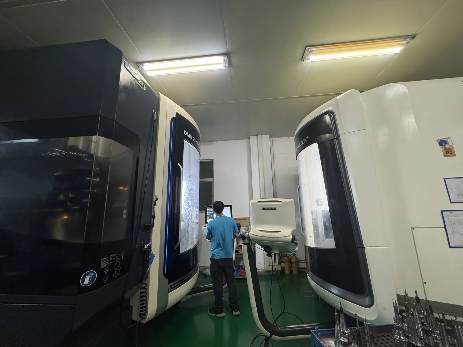
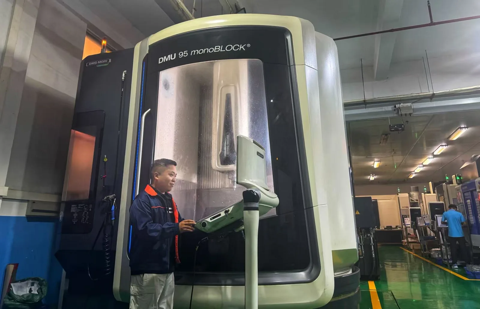
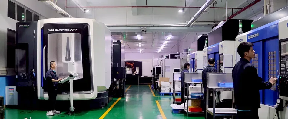
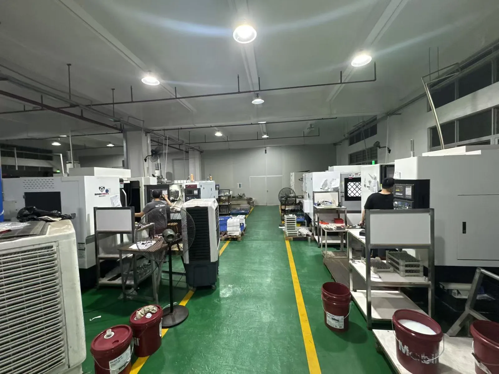
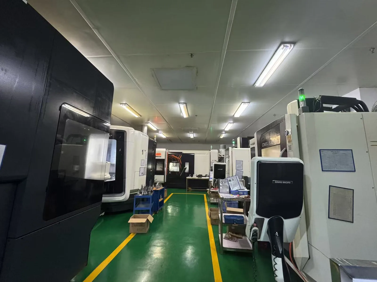
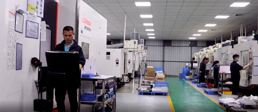
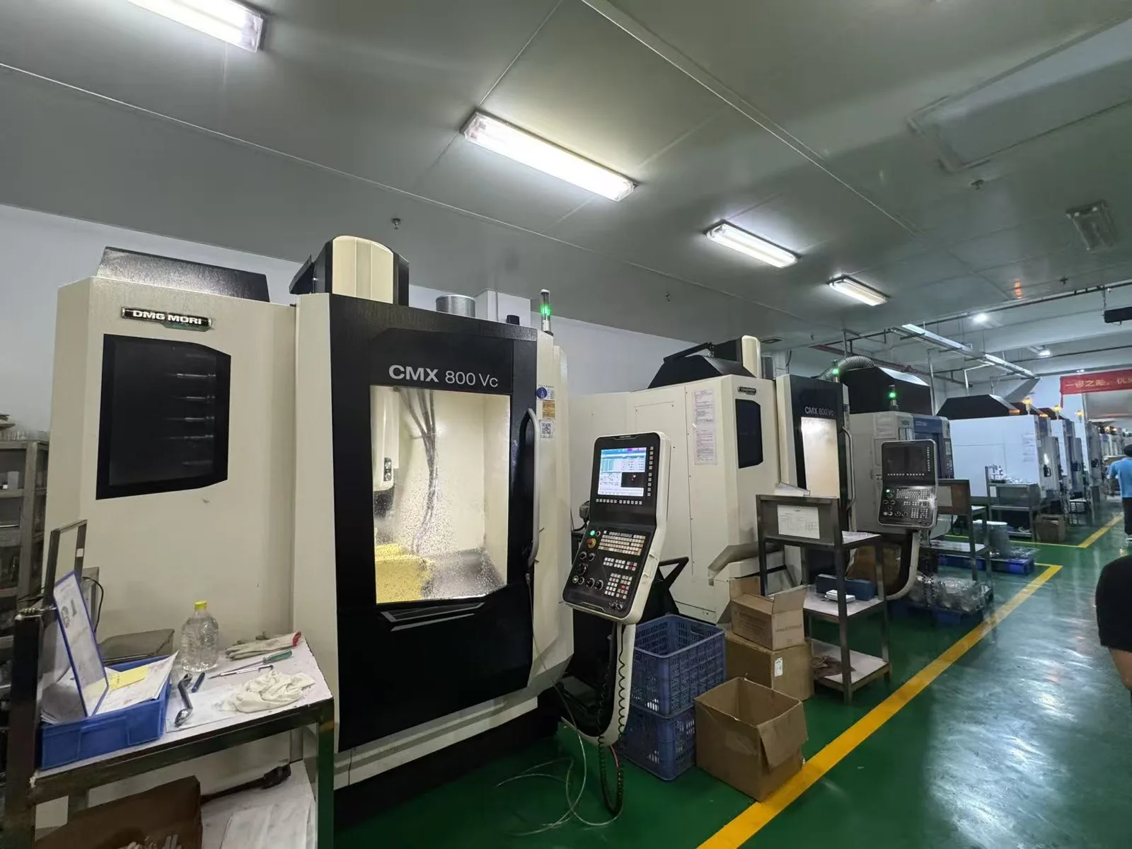
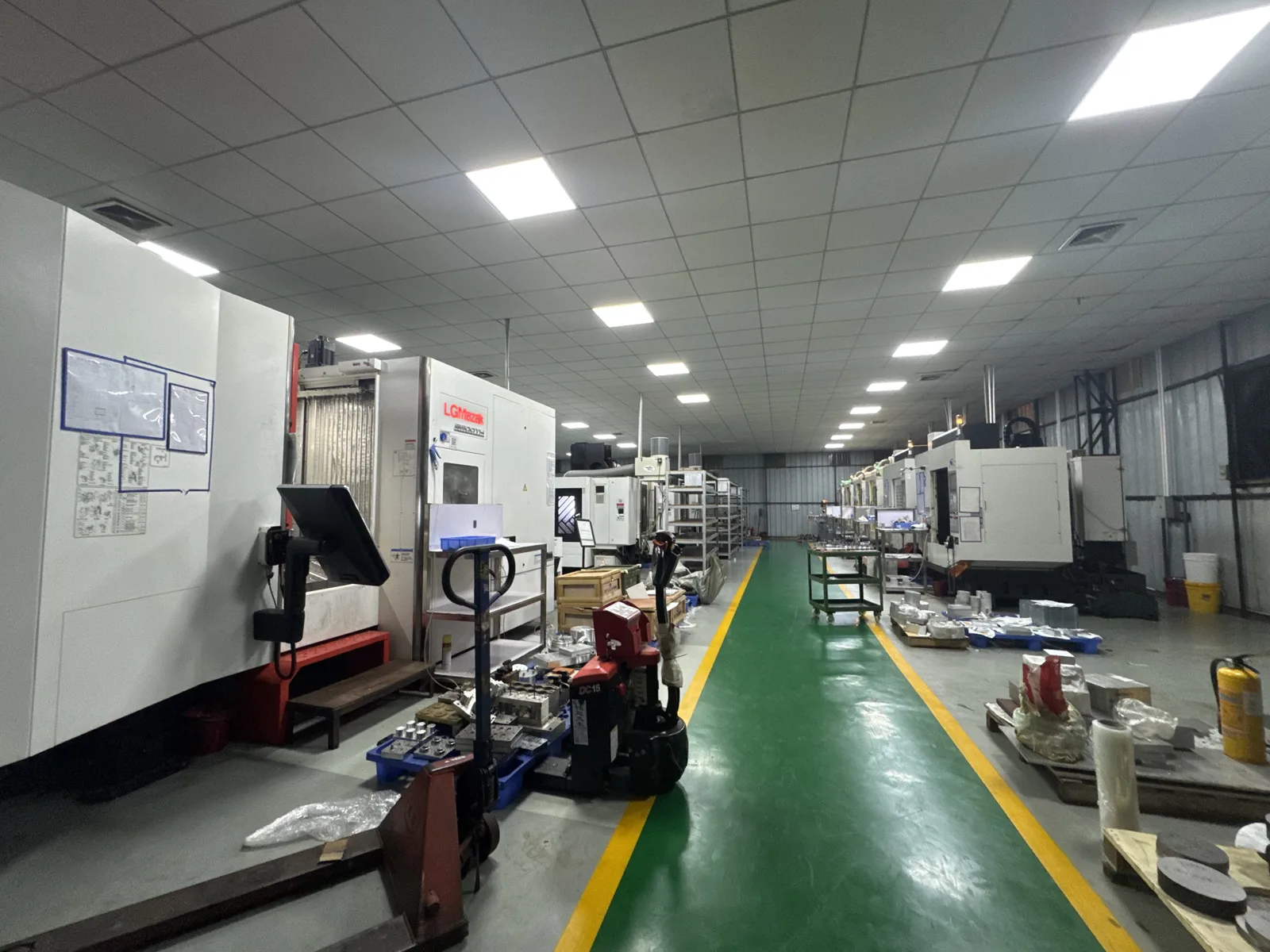
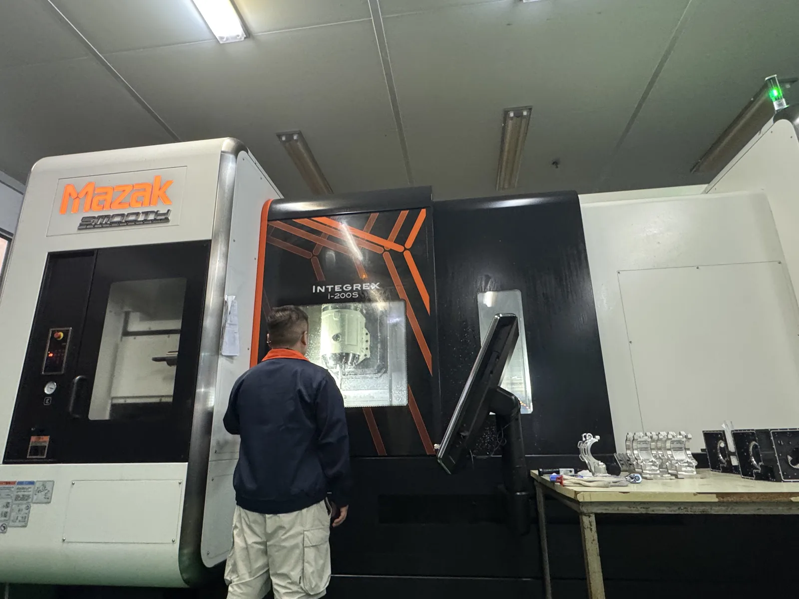
BatchMach Precision machines PEEK parts using 3-axis, 4-axis, and 5-axis machining centers, CNC lathes, and mill-turn equipment. The process is selected based on part geometry, tolerances, workholding, and production quantity. Because PEEK is costly and sensitive to heat and internal stress, we plan datums, machining sequences, and inspection stages in advance to reduce setups, control distortion, and improve material utilization.

5-Axis Machining Centers

5-Axis Machining Centers

DMU 95 CNC Machining

DMU 95 CNC Machining

DMG MORI Workshop

DMG MORI Workshop

CNC Machining Workshop

CNC Machining Workshop

CNC Production Line

CNC Production Line

CNC Production Workshop

CNC Production Workshop

Large-Part CNC Workshop

Large-Part CNC Workshop

Large-Part Machining

Large-Part Machining

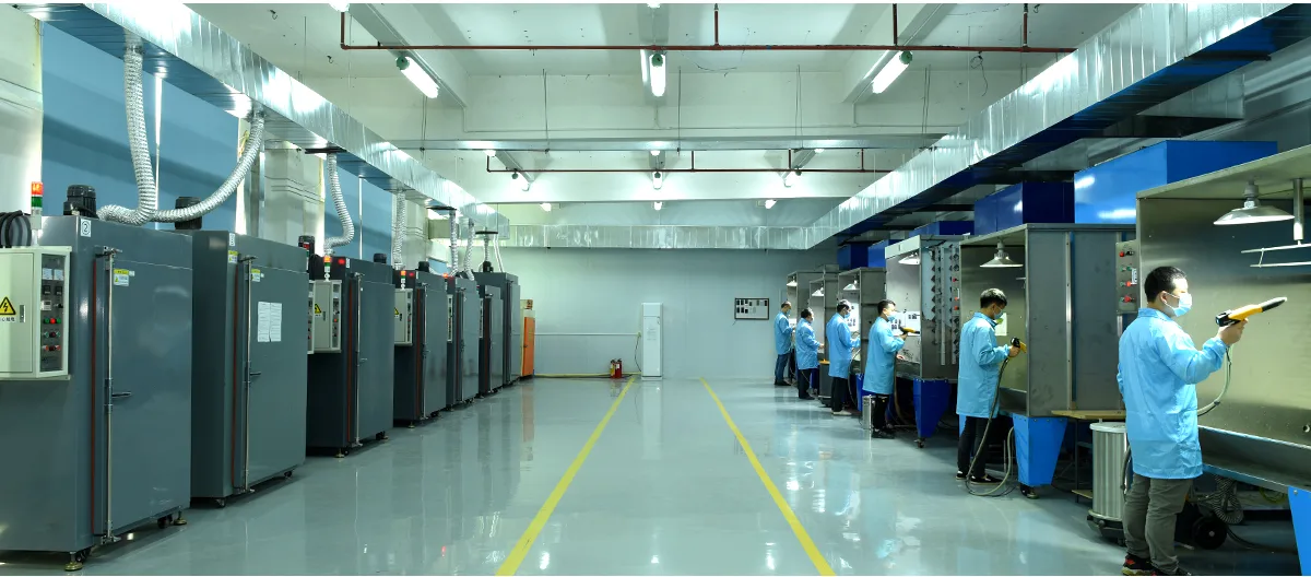
Powder Coating Workshop

Powder Coating Workshop

Quality Control for CNC-Machined PEEK Parts

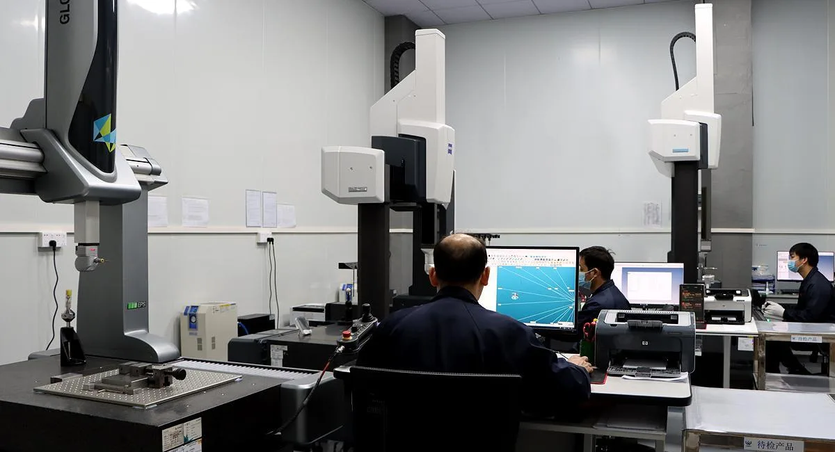
PEEK inspection requires more than checking dimensions after machining. Material grade, temperature, part support, measuring force, and the time between machining and inspection can all affect the result. BatchMach Precision defines the inspection method according to the drawing, part rigidity, and functional requirements.
Material and Drawing Verification

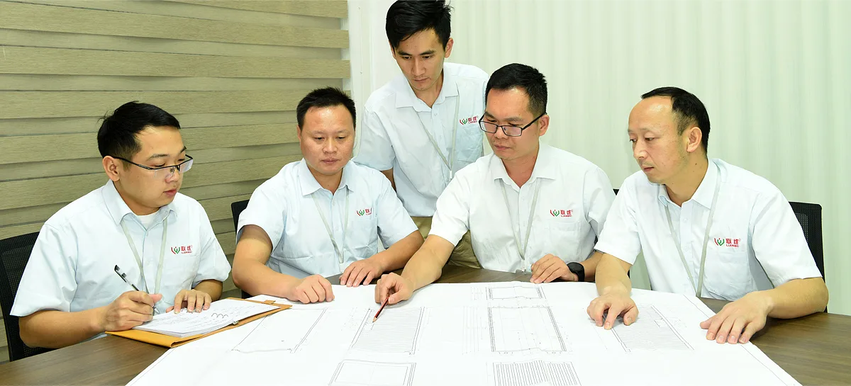
Before machining, the specified PEEK grade, stock form, drawing revision, dimensions, datums, and inspection requirements are reviewed. Requirements for material certificates, batch traceability, or regulatory documentation should be identified during the RFQ stage. This prevents an unfilled, reinforced, bearing, or application-specific grade from being treated as interchangeable.

First-Part and In-Process Inspection

Critical dimensions are checked during production rather than left until final inspection. Features affected by clamping, heavy stock removal, or thin-wall movement may be measured after roughing and again after finishing. This allows offsets or process steps to be reviewed before the remaining parts are completed.

Final Dimensional and Visual Inspection

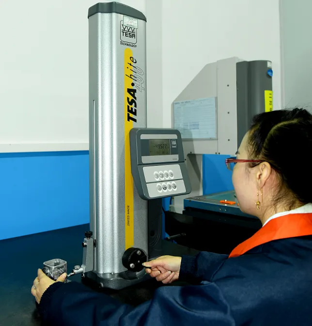
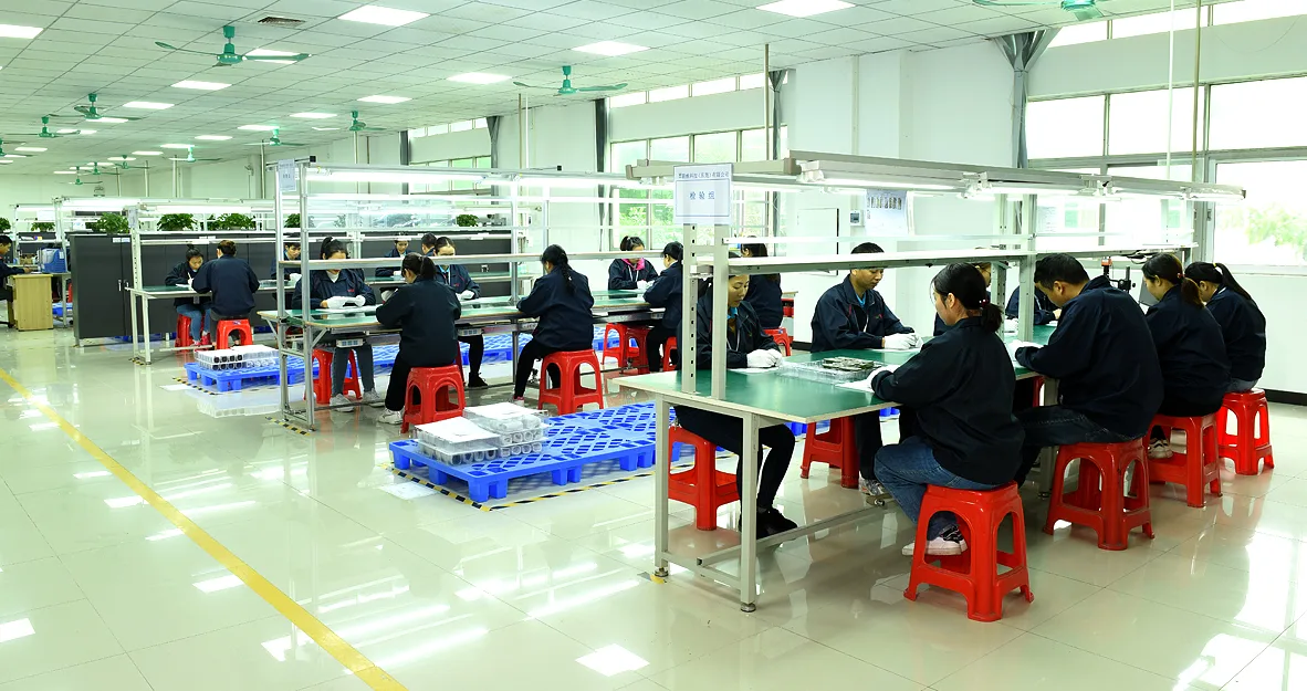
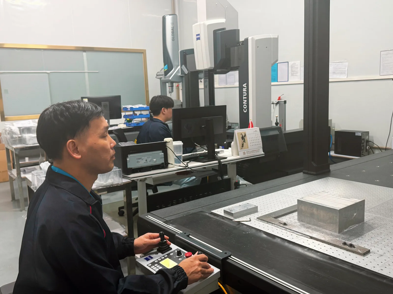
Features suitable for coordinate measurement can be inspected using ZEISS CONTURA or Hexagon CMM equipment. TESA height gauges, vision-measuring systems, and Mitutoyo precision instruments are used according to the feature type and tolerance. Final inspection also covers threads, edges, burrs, surface condition, and drawing-defined geometric requirements. Thin-walled parts are supported appropriately to reduce measurement-induced deformation.

Quality Control for CNC-Machined PEEK Parts

Why Choose BatchMach Precision for PEEK CNC Machining?

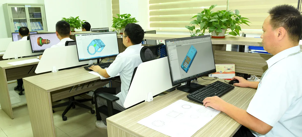
A PEEK machining plan cannot be determined by the material name alone. Part geometry, grade, stock condition, material-removal ratio, datum structure, and inspection requirements can all affect the final result. BatchMach Precision reviews these factors before quoting and production to reduce distortion, unnecessary setups, and material waste.

Machining Processes Selected for the Part Geometry

/01

Machining Processes Selected for the Part Geometry

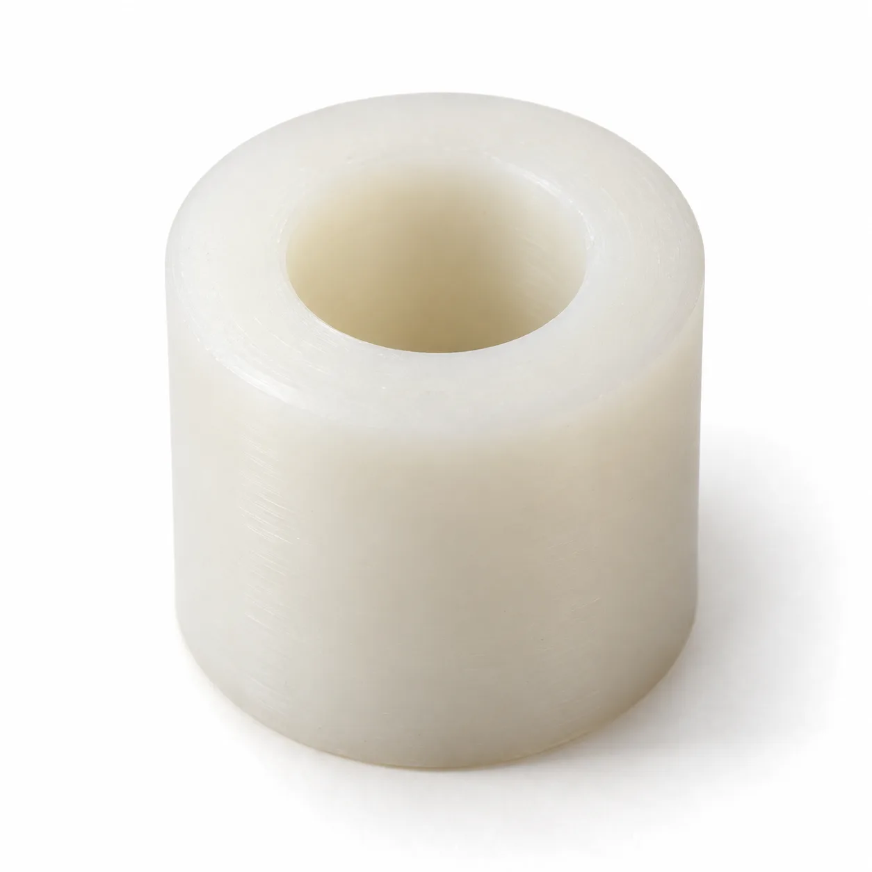
BatchMach Precision provides three-axis, four-axis, five-axis, horizontal, CNC turning, and mill-turn machining. The process is selected according to rotational features, multi-face geometry, tool access, and datum requirements. When completing multiple features in one setup provides a clear advantage, DMG MORI or Mazak five-axis equipment can be used to reduce repositioning and datum-transfer error.
Material and Distortion Review Before Machining

/02

Material and Distortion Review Before Machining

Our engineering review considers the PEEK grade, stock form, wall thickness, pockets, material-removal balance, and critical tolerances. Thin-walled, asymmetric, or heavily machined parts may require a planned workholding strategy, separate roughing and finishing operations, or intermediate annealing. Applying tight tolerances only to functional features can also reduce material use and machining cost.

Inspection Based on Functional Requirements

/03

Inspection Based on Functional Requirements

Inspection methods are selected according to the critical dimensions, datums, and geometric tolerances identified on the drawing. Features suitable for coordinate measurement can be verified using ZEISS CONTURA or Hexagon CMM equipment. TESA height gauges, vision-measuring systems, and Mitutoyo precision instruments are available for other dimensional requirements. Thin-walled PEEK parts also require suitable inspection support and controlled contact force.

Ready to start your next machining project?

Get a Quote

Start Your PEEK Machining Project

Send Us Your Requirements

Send us your 3D model, 2D drawing, PEEK grade, quantity, and operating conditions. We will review the stock material, machining process, inspection requirements, and primary manufacturing risks before quoting.

Inspection Documentation

Specify any required inspection report, material documentation, sampling plan, or traceability requirement with your RFQ so it can be included in the manufacturing and inspection plan.

PEEK CNC Machining FAQ

PEEK can be milled, turned, and machined in multiple axes, but internal stress, cutting heat, clamping pressure, and stock-removal strategy can affect final dimensions. Thin-walled, asymmetric, or heavily pocketed parts are more likely to move during machining or after unclamping. The process may require controlled clamping pressure, sharp cutting tools, balanced material removal, and separate roughing and finishing operations.

CNC machining requires no mold tooling, making it practical for functional prototypes, design revisions, and low-volume production. Injection molding may become more economical at higher quantities, but it requires tooling investment and careful control of material drying, melt temperature, and mold temperature. Another option is to produce a near-net blank and finish-machine the critical bores, mating surfaces, or other functional features.

There is no universal machining tolerance for all PEEK parts. BatchMach Precision reviews the part size, wall thickness, material grade, stock condition, datum structure, and material-removal ratio before selecting milling, turning, five-axis, or mill-turn machining. Critical dimensions and geometric tolerances may be verified using ZEISS CONTURA or Hexagon CMM equipment when appropriate. Final achievable tolerances must be confirmed from the part geometry and inspection requirements.
The main cost factors include the PEEK grade, stock size, material utilization, machining time, number of setups, tool wear, tolerance requirements, inspection work, and any intermediate annealing. Glass- and carbon-filled grades may increase tool wear. Choosing an appropriate stock size, reducing unnecessary material removal, and applying tight tolerances only to functional features can help control manufacturing cost.

Not every PEEK part requires an additional annealing cycle. Intermediate annealing may be considered for thin walls, asymmetric geometry, tight tolerances, extensive one-sided stock removal, or fiber-reinforced grades. A typical approach is to rough-machine the part, leave finishing allowance, anneal it according to the material supplier’s recommendations, and then complete the final dimensions. Annealing parameters should not be applied without considering the exact grade and stock condition.

Unfilled PEEK is commonly selected when toughness, electrical insulation, and chemical resistance are priorities. Glass-filled PEEK provides greater stiffness and creep resistance, while carbon-filled PEEK generally offers higher stiffness and lower thermal expansion. Bearing-grade PEEK is formulated for sliding and wear conditions. Selection should also consider fiber orientation, mating materials, operating temperature, and electrical requirements. The exact brand and grade should be verified against the supplier’s technical data sheet.

PEEK can replace certain metals when weight reduction, chemical resistance, electrical insulation, or the elimination of metal contact is important. However, PEEK differs from metal in stiffness, creep behavior, thermal expansion, and load capacity, so replacement decisions should not be based on tensile strength alone. Operating temperature, sustained load, pressure, impact, assembly method, and allowable deformation must be reviewed. Design changes or a fiber-reinforced PEEK grade may be required.

Free first-order sample for new customers

Send your drawings today — get a free process evaluation, quotation within 24 hours, and flexible quarterly settlement for long-term partners.

Upload Drawing & Get Quote